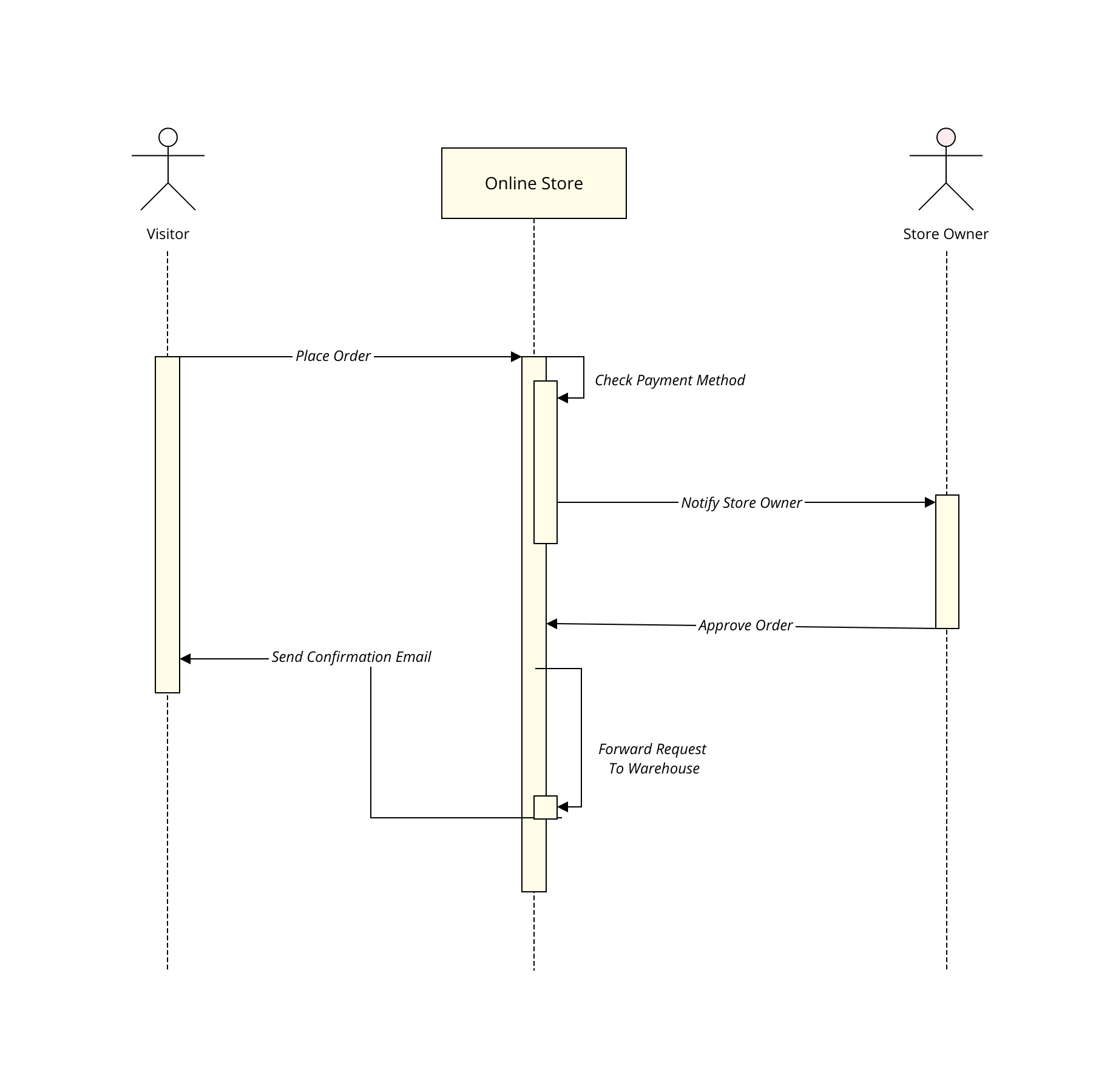


The sequence diagram has only two basic symbols: object and focus of control. Let’s start with an overview of basic symbols: The sequence diagram depicts the objects involved in the scenario and the sequence of messages exchanged between them required to execute the functionality. These diagrams are the VIP guests of each feature-related meeting.
#Sequence diagram uml software
It’s a contract between me and other involved guys, such as product manager, software architect, team members, etc. I’m creating this diagram before I start to design implementation, just to understand the requirements. In my opinion, a sequence diagram is best to represent cross-services end-to-end scenarios or specific flow (or part of it) within a particular service. If an adult saw a lumpy hat, the Narrator spoke about golf and bridge and politics he never mentioned jungles or boa constrictors or stars. As an adult, he used the boa drawing to decide what topics to talk about with other adults. The child grew up, became a pilot, and flew worldwide (not the worst). When he showed it to adults, they all thought it was a lumpy hat and suggested he stop messing about and study the “important subjects” in school instead. Here is a boa roentgen, if you have any doubts. He drew a picture of the boa in this state. Okay, briefly, when he was a child, the Narrator read a book on jungles and was fascinated by the fact that a boa constructor swallows his prey whole and then sleeps for few months while digesting the meal. I will summarise only the part that is relevant to the current article. Have you read Antoine de Saint-Exupéry’s novel? In this article, I’m about to show you the notations of these interactions through “The Little Prince” narrator’s interactions with the world around him. In general, a Sequence diagram describes how and in what order objects in our system interact with each other, arranged in time sequence. Implementation designs of each new feature I’m working on are loaded with Sequence diagrams. Lifelines may begin with a labeled rectangle shape or an actor symbol.The most used by me (and my favorite) UML diagram is Sequence Diagram. A dashed line, known as a lifeline, represents events in an SSD. Within a SSD, this shape models the system as a black box (a system with inner workings that are not immediately visible).Īctors - shown by stick figures, actors are entities that interact with the system, and yet are external to it.Įvents - the system events that the actors generate in the sequence. Objects - this box shape with an underlined title represents a class, or object, in UML. Most elements we cover in use case diagrams remain in use throughout a system sequence diagram, including: Use case diagrams are simply another diagram type which represents a user's interaction with the system. Standard sequence diagrams show the progression of events over a certain amount of time, while system sequence diagrams go a step further and present sequences for specific use cases. This language provides a toolkit for diagram creators to make and read diagrams that are comprehensible regardless of location or industry. System sequence diagrams, also known as SSD, are actually a sub-type of sequence diagrams, whose style and notation is dictated by the Unified Modeling Language.


 0 kommentar(er)
